Calculating fault geometry properties with the QC tool
With the Calculate Fault Geometry Properties form (Model > 3D Structure > QC > Calculate Fault Geometry Properties) you can calculate fault displacement properties for your faults, i.e. fault throw, fault heave and fault dip displacement. The purpose of this tool is to be able to visually QC the fault displacement, which can be important in structurally complex fields.
To calculate these properties, you need to have fault cutoff lines available under your 3D Structural Model > Fault Cutoff Line Edits item in the JewelExplorer. If you don't have fault cutoff lines, calculate them first with the Fault Cutoff Line Edits form of the Structural Modeling workflow. By visualizing the fault geometry properties on your faults in the 3D View, you can QC the consistency of the fault displacement.
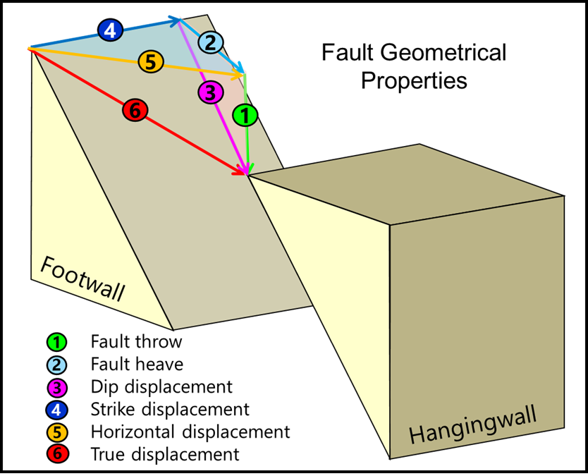
Schematic diagram of an oblique fault with the components fault throw (vertical component), fault heave (stratigraphic apparent horizontal component) and dip displacement (dip-parallel slip component) indicated with the numbers 1, 2 and 3. click to enlarge
To calculate the fault geometry properties
Before you start, make sure you have fault cutoff lines available under your structural model in the JewelExplorer (a requirement for the calculation of fault geometry properties).
- On the Calculate Fault Geometry Properties form, select a structural model in the Model drop-down list.
- Select one or more faults in the Fault column at the left side of the form for which you want to calculate the fault geometry properties (all faults in the selected structural model are listed).
- Under Properties at the right side of the form, select the fault geometry properties that you want to calculate. See the image above for a graphical explanation of each of these properties.
- Click Apply (and keep the form open) or OK to calculate the properties.
- The calculated fault geometry properties will be added to the fault in the 3D Structural Model. To QC the fault displacement, visualize the fault(s) in the 3D View and select the relevant property (see example below).
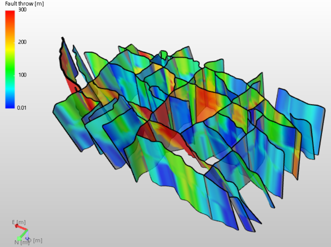
Example of a complex structural model with the fault throw property visualized on the faults. click to enlarge